
انجام تست التراسونیک جوش فورجینگ میلگرد و صدور تاییدیه
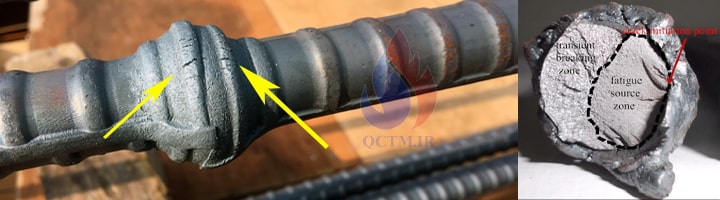
جوشکاری فورجینگ یکی از روش های رایج و مؤثر برای اتصال میلگردهای آجدار در سازه های بتن مسلح می باشد. در این روش دو میلگرد با اعمال همزمان فشار و حرارت به یکدیگر متصل می شوند و برای حصول اطمینان از سلامت جوش ها از تست التراسونیک جوش فورجینگ میلگرد استفاده می شود.
با توجه به اهمیت استحکام این نوع اتصالات در ایمنی کلی سازه، کنترل کیفیت آن ها امری ضروری است. از این رو، آزمون التراسونیک (UT) طبق استاندارد بینالمللی JIS Z 3062 جهت ارزیابی کامل ناحیه جوش انجام می شود. این تست، امکان شناسایی دقیق هرگونه ناپیوستگی یا عیب داخلی را فراهم کرده و نقش مهمی در تضمین کیفیت و ایمنی اتصال ها ایفا می کند.
ارائه خدمات آزمایشات غیر مخرب :
- انجام بازرسی چشمی VT بر روی جوش های فورجینگ
- انجام تست التراسونیک UT بر روی جوش های فورجینگ میلگرد
- انجام تست های جوش فورجینگ میلگرد و صدور تاییدیه جوش فورجینگ
تعرفه تست التراسونیک جوش فورجینگ میلگرد (هزینه آزمایش فورجینگ)
| شرح خدمات | مبلغ (تومان) |
|---|---|
| آزمایش التراسونیک (UT) به ازای هر اینچ قطر | ۱۳۵,۰۰۰ |
| آزمایش التراسونیک (UT) به ازای هر متر طول | ۹۰۰,۰۰۰ |
| آزمایش التراسونیک (UT) به ازای هر متر مربع | ۱,۱۲۵,۰۰۰ |
هدف از تست التراسونیک UT
شناسایی عیوبی مانند :
- عدم ذوب کامل میلگردها (lack of fusion or LOF)
- ترک در ناحیه جوش (crack)
- وجود حفره یا آخال (porosity or inclusion)
- ارزیابی یکنواختی و تداوم جوش در تمام سطح مقطع
استانداردهای مرتبط با جوش فورجینگ :
- مبحث نهم مقررات ملی ساختمان (طراحی و اجرای ساختمان های بتن آرمه)
- نشریه ۹۷ سازمان مدیریت و برنامه ریزی کشور (راهنمای طراحی و اجرای سازه های بتن آرمه)
- نشریه ۲۸۳ (راهنمای بازرسی جوش میلگرد)
- آییننامه بتن ایران (آبا)
- استاندارد ژاپنی JIS Z 3062
Method and acceptance criteria of ultrasonic examination for gas pressure welds of deformed steel bars for concrete reinforcement.
دستورالعمل انجام تست التراسونیک جوشکاری فورجینگ سر به سر میلگرد
جزئیات این دستورالعمل توسط کمیته آموزش، تحقیق و توسعه انجمن صنفی جوشکاران فورجینگ سر به سر میلگرد تهیه شده است و مطابق با استاندارد JIS 3062 می باشد.
ملزومات انجام تست التراسونیک
- مطالعه استاندارد 3062 JIS مربوط به بازرسی التراسونیک بر روی میلگردها
- استفاده از روش فرستنده و گیرنده (PROBE ULTRASONIC TR)
- استفاده از پروب با فرکانس 5 مگاهرتز
- استفاده از پروب با قطر کريستال 5 * 5 میلیمتر
- استفاده از پروب با زاويه 7۰ درجه
روش تست التراسونیک جوشکاری فورجینگ سر به سر میلگرد
8.1 Examination method
The flaw detection shall be performed by angle beam double probes on ribs of the steel bar on both sides of a swelling of pressure weld (see figure 3).
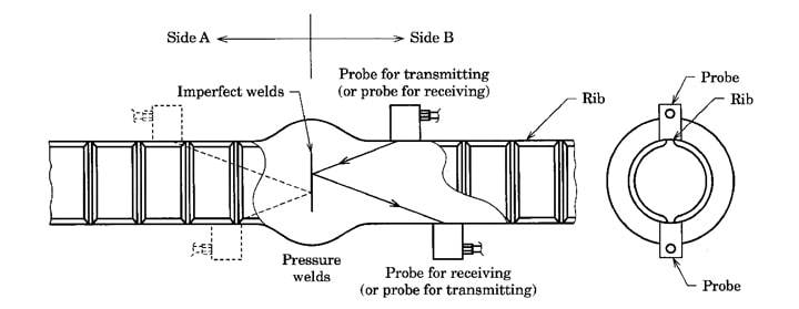
Table C.I Performances of probe
| Measuring method and description | Performances | Item |
| 5mmx5mm | Normal transducer size |
| Measuring method and description | Performances | Item |
| The centre frequency shall be measured by using an echo signal from R50 portion of RB-PW reference block described in Annex E in accordance with JIS Z 2350 | 5MHz± 1 MHz | Test frequency |
| Measuring method and description | Performances | Item |
| The length shall be measured by using portion of R50 of RB-PW reference block The length means the distance from edge of probe to probe index | 10mm max | Approachable limit length |
| Measuring method and description | Performances | Item |
| The angle shall be measured by using a drilled through hole of 8 mm dia. of RB-PW reference block | 70°±2° | Refraction angle |
| Measuring method and description | Performances | Item |
| Sr =S1 – S2 where, S 1 : S 1 is the indication of gain controls when the instrument gain is increased as high as possible in the range where noise level in gate is not more than 10 % of display graticule, under the condition where a probe is connected to the test instrument S2 : S2 is the indication of gain controls when the instrument gain is adjusted to set the amplitude of echo from an 8 mm dia through hole of RB-PW reference block to 50 % display graticule | 30dB min | Sensitivity (Sr) |
| Measuring method and description | Performances | Item |
| 12mm±2mm | Length of contacting face | |
| 2m max | Length of probe cable |
روش کالیبراسیون دستگاه تست التراسونیک
D.3 Check of performances
D.3.1 Check of sensitivity and refraction angle
The sensitivity and refraction angle are checked by the following methods
| a) The reference block RB-PW specified in Annex E is used to check the sensitivity and refraction angle |
| b) The check is performed by the following procedures Set the gate setting of the test instrument to nominal designation “D41” Each probe is arranged to the predecided positions of the reference block as shown in figure D.1 |
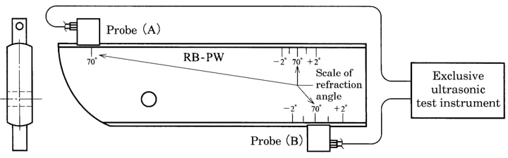
| Adjust the incident point of the probe (A) at the time of manufacture shipment to “70°” on refraction angle scale of the reference block and fix it Perform depth scanning using another probe (B) and fix such that the level of transmitted pulse becomes maximum with the alarm lamp, bar display or sound of the test instrument, etc., and read the refraction angle scale using the incident point of the probe (B) at the time of manufacture shipment |
| Read the value of the gain control holding its status as measurement of the refraction angle. Obtain the difference between this value and that of the maximum sensitivity of the gain control and take the absolute value of thedifference as the margin of detection sensitivity. At the time when setting the gain control to the maximum sensitivity and getting off the probe of the reference block, however, confirm that no alarm sounds. In the case where alarm sounds, lower the sensitivity of the gain control to the point where no alarm sounds, and take the value at the point as the maximum sensitivity of the gain control and then obtain the margin of detection sensitivity |
| It shall be confirmed that the margin of detection sensitivity and refraction angle exist in the following range |
| Margin of detection sensitivity 10 dB min |
| Tolerance of refraction angle of probe Within ± 2° |
حدود پذیرش (Acceptance Criteria) :
| 7.3 Set of acceptance level The level which shall be obtained by decreasing 24 dB from the reference level is taken as the acceptance level Acceptance Level = Reference Level – 24 dB |
بدین معنی که سطح پذیرش (Acceptance Level) برابر است با ۲۴ دسیبل کمتر از سطح مرجع (Reference Level).
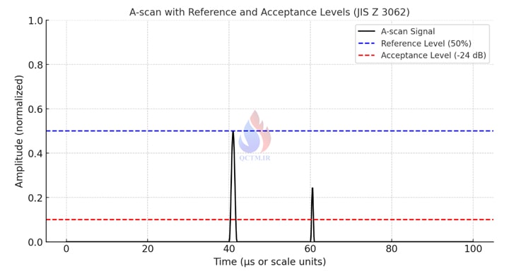
🔴 خط قرمز = سطح پذیرش (24db-)
مثال
فرض کنید در کالیبراسیون مرجع :
دامنه سیگنال مرجع (Reference) روی 50% ارتفاع صفحه A-scan تنظیم شده باشد.
دستگاه در این شرایط Gain = 30 dB نشان میدهد.
مطابق با فرمول :
6 = Acceptance Level = 30 dB – 24 dB
یعنی اگر سیگنالی قوی تر از 6 دسی بل ظاهر شود قابل قبول نیست.
اگر ضعیف تر از 6 دسی بل باشد قابل قبول است.
جهت هر گونه درخواست و مشاوره رایگان با شماره تلفن های زیر تماس حاصل فرمایید.
| تلفن : ۳۰۸ ۳۰۷ ۹۱ – ۰۲۱ موبایل : ۱۰ ۸۰ ۶۴۵ ۰۹۱۲ |


سلام
خیلی متن خوب و کاملب بود ممنون از راهنمایی شما
من همیشه به سایت شما سر میزنم
خداقوت